|
|
|
Porsche, and the Porsche crest are registered trademarks of Dr. Ing. h.c. F. Porsche AG.
This site is not affiliated with Porsche in any way. Its only purpose is to provide an online forum for car enthusiasts. All other trademarks are property of their respective owners. |
|
|

  |

| 76-914 |
 Dec 1 2013, 09:49 PM Dec 1 2013, 09:49 PM
Post
#181
|
|
Repeat Offender & Resident Subaru Antagonist  Group: Members Posts: 13,502 Joined: 23-January 09 From: Temecula, CA Member No.: 9,964 Region Association: Southern California |
Sorry Chris, I missed your response earlier. Yes, they are 6" too long but no big deal.
I got back to the gas tank today and finished it. It was fun but I'm glad it's over. Maybe I should have left it with the delivery system it had used previously but this Subaru pump is up to date, easily available, cheap and #1 safer! Lots of prep time measuring. The old adage "measure twice cut once" was never truer. I got azzhole lucky and everything fit. I saw this setup in a pic somewhere, liked it and copied it. It is Bob's (BIGKAT) idea to use the Impreza pump and relocating OEM sender. I didn't have the measurements when I began but I do now. If you go the same route hit me up I'll share them. As mentioned in another thread I welded the ends closed on the tank nipples. 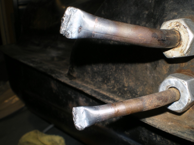 The last mod to this tank will be to relocate the fuel sender. I need the new location to clear the hold down strap and the new fuel pump assembly while staying in line with the "channel" or deepest part. The tank baffle is within an inch of the sender so watch it! I used the old seal to mark for the cut out and bolt hole location. 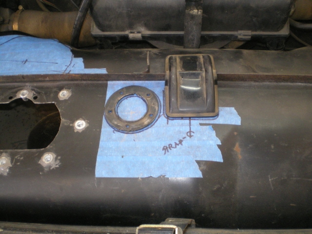 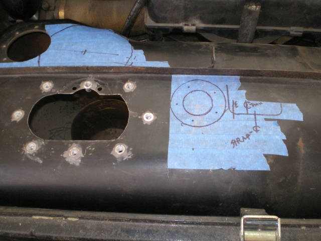 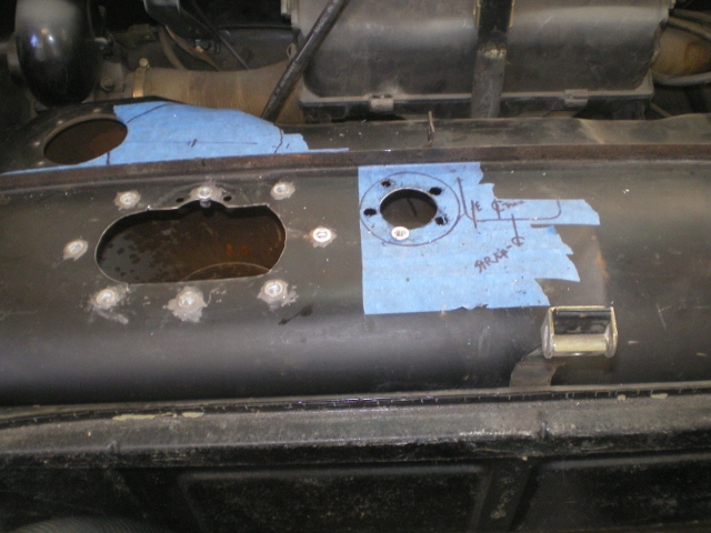 Here the holes are prep'd for JB Weld on the rivenuts. 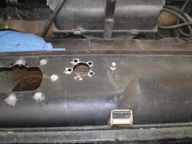 After the epoxy has set it is test fit with the new cork gasket. 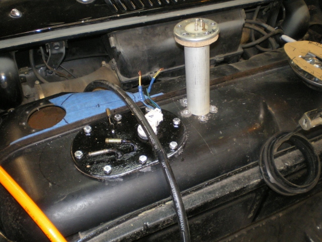 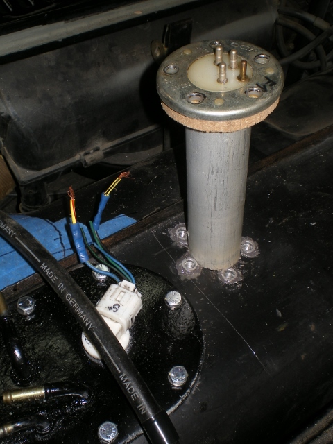 This is a fender washer that I cut to retain the screen pick up which I had to rotate 180 degrees to fit inside the "bucket" section of the tank. This bucket is where the old tank outlet was. Once the screen was rotated the part which had held it in place is now sticking out with nothing to hold it down. Hence this horseshoe piece is riveted in place and holds down that unsupported part is now captured. You can see it beneath the washer. It's a white plastic piece. 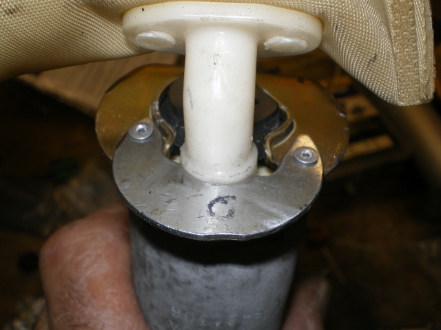 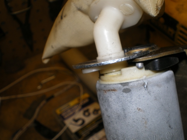 Clean tank, reassemble, strap down, connect fuel sender and temp wire nut pump. 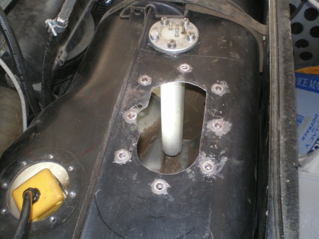 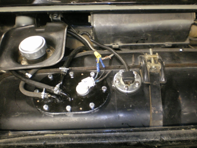 Attached image(s) 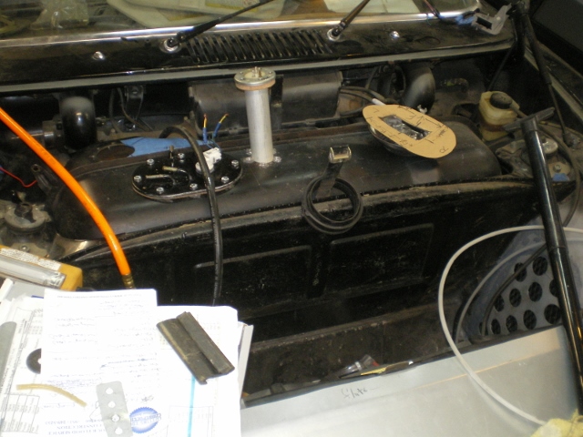 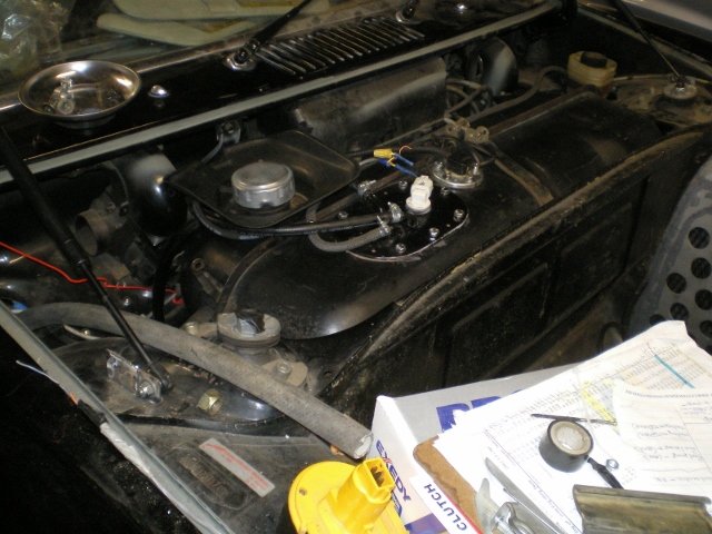
|
   |

 
|
| 76-914 |
Dec 12 2013, 11:06 PM
Post
#182
|
|
Repeat Offender & Resident Subaru Antagonist Group: Members Posts: 13,502 Joined: 23-January 09 From: Temecula, CA Member No.: 9,964 Region Association: Southern California |
Something new. I wired the fan system and learned a great deal in the process. It's covered in this thread. http://www.914world.com/bbs2/index.php?showtopic=226470 If your going twin fan there is an excellent schematic shown there and it would behoove you to print it. I ran 14ga wire and placed it in the some loom that I pulled from the donor. The only thing left is to pull the tank so I can run the harness beneath the tank then up to the relay bank. The green & black wires now running over the tank will be under it and trimmed to final length.
Got a grommet in place and ran this 8ga thru 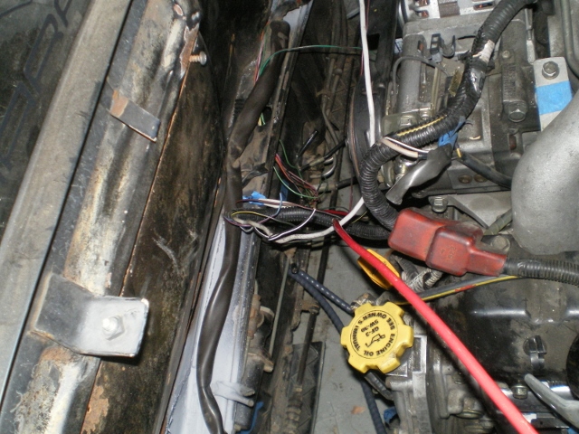 Up thru the tunnel 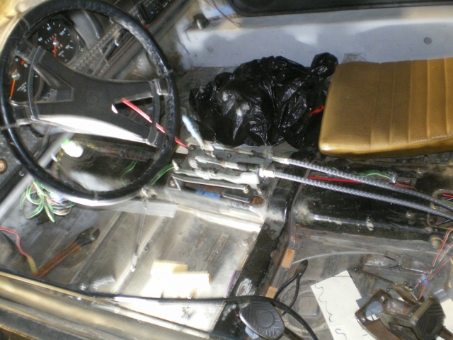 and out thru another grommet 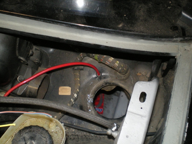 to 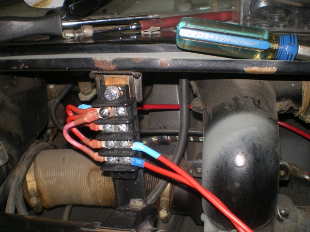 to 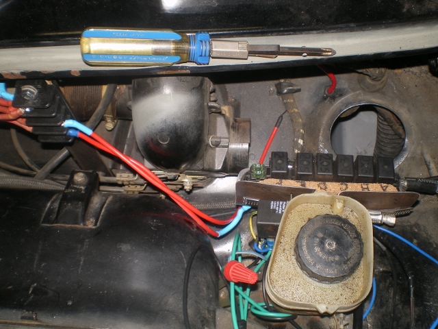 to my relay block that I lifted from the donor car. It has 2 30 amp fuses that are used on 3 of these relays. The others will need their own fuses. The relay that sits off to the side is the 5 pole (DTSP?) relay. It all mounts to the reservoir bracket after the speed clip is removed and a 6061 sleeve/bolt is used in place. 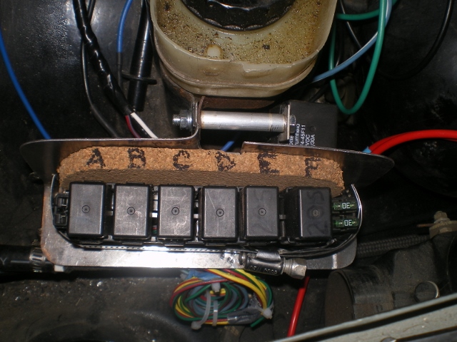 The blue wires on the right are the hi & lo speed switch wires, and remainder are wired into existing ign system. The Bk and Gr wires on the left side are the 14 ga wires to the fans. 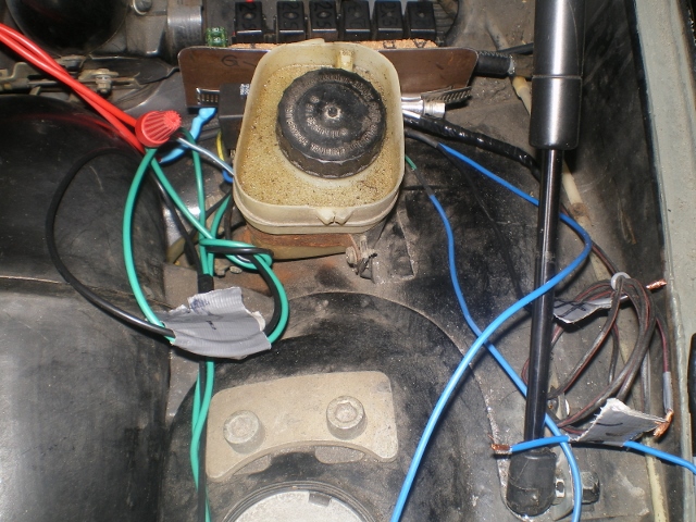 Attached image(s) 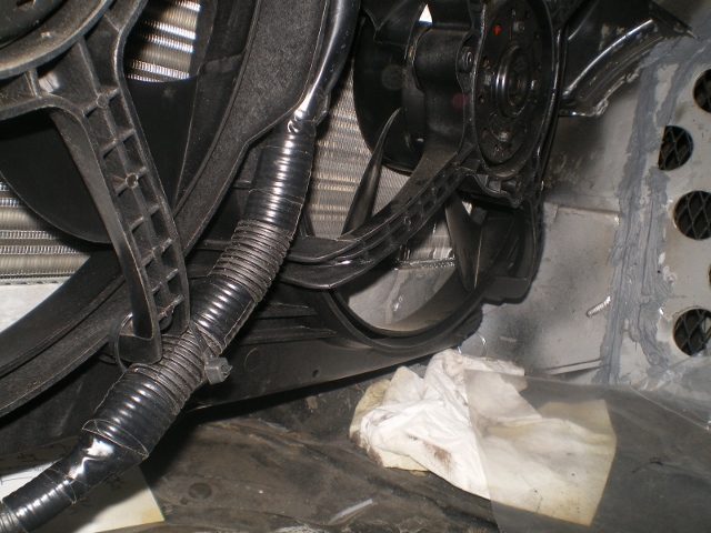 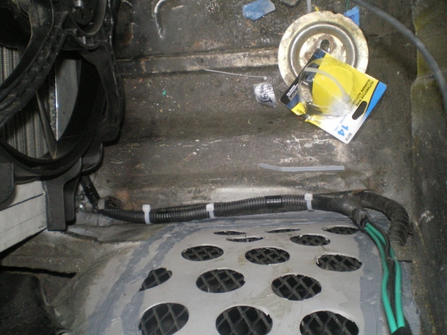
|
|
|
|
| Chris H. |
Dec 13 2013, 07:25 AM
Post
#183
|
|
Senior Member Group: Members Posts: 4,030 Joined: 2-January 03 From: Chicago 'burbs Member No.: 73 Region Association: Upper MidWest |
Great work! You might DRIVE that thing soon! What's next? Hydraulic clutch?
|
|
|
|
| CptTripps |
Dec 13 2013, 10:29 AM
Post
#184
|
|
:: Punch and Pie :: Group: Members Posts: 3,584 Joined: 26-December 04 From: Mentor, OH Member No.: 3,342 Region Association: Upper MidWest |
QUOTE(76-914 @ Nov 23 2013, 10:48 PM)  I was able to finish up with the shifter fab today so I thought I'd throw out a few dimensions here 'n there for others.... Awesome post man. Thanks! If Ian isn't able to get something going, I'll be building one just like this for myself. How about a few angles on the part that connects to the shift rod? |
|
|
|
| 76-914 |
Dec 13 2013, 12:06 PM
Post
#185
|
|
Repeat Offender & Resident Subaru Antagonist Group: Members Posts: 13,502 Joined: 23-January 09 From: Temecula, CA Member No.: 9,964 Region Association: Southern California |
Hey Chris, This is what still needs to be done, AFAIK. I have the 1/2 shafts to convert; test ECU wiring; make a intake breather; clutch conversion. I usually choose the most daunting task so it's not there to haunt me. Given that, I'll probably do the clutch next (IMG:style_emoticons/default/biggrin.gif) Have any tips or info for me re: the clutch? I'm all ears. I've read PCR's post on converting. Which route are you headed?
Hey Doug, Let me know if this answers your question. See post #175. There are 2 pieces that have an angle. First is the 1" wide piece of the angle that the cable (running parallel with the trans) passes thru. Before it is welded on it is placed in a vice and compressed or splayed 15 degrees more for a total of 105 degrees. This angle places the cable in line with the shift rod angle. This same piece is welded in place with a 20 degree offset to place the cable end as close as possible to the shift rod. The other piece is the one with two holes drilled in it where the bracket attaches to the tranny. There is a 2mm difference between the center of those two holes which sets the 3rd angle. |
|
|
|
| Chris H. |
Dec 13 2013, 01:18 PM
Post
#186
|
|
Senior Member Group: Members Posts: 4,030 Joined: 2-January 03 From: Chicago 'burbs Member No.: 73 Region Association: Upper MidWest |
Of course I haven't started the clutch but I do have the parts...
Now for the shocker...I COPIED MIKE BELLIS AND BIGKAT. My plan is to use a Wilwood master cylinder push style (3/4 but we'll talk about that later) with Aeroquip -3AN braided hose with a threaded pressure fitting at the MC end and the required 10mm banjo fitting at the slave cylinder end (using the stock slave cylinder). Have to fab up something at the pedal cluster to compress the master when the clutch is pushed. In most cases they say match your slave and master cylinders but you really don't have to because the clutch throw will be different. I think Bob mentioned he wished he had a 5/8 at one point and if he has the stock slave it's an 11/16 or 3/4. Might not make much of a difference....I have the part numbers for the fittings and stuff if you need 'em. Which way are you going on the half shafts? Subie inners and re-splining the axles? |
|
|
|
| 76-914 |
Dec 14 2013, 10:15 AM
Post
#187
|
|
Repeat Offender & Resident Subaru Antagonist Group: Members Posts: 13,502 Joined: 23-January 09 From: Temecula, CA Member No.: 9,964 Region Association: Southern California |
QUOTE(Chris H. @ Dec 13 2013, 11:18 AM) Of course I haven't started the clutch but I do have the parts... Now for the shocker...I COPIED MIKE BELLIS AND BIGKAT. My plan is to use a Wilwood master cylinder push style (3/4 but we'll talk about that later) with Aeroquip -3AN braided hose with a threaded pressure fitting at the MC end and the required 10mm banjo fitting at the slave cylinder end (using the stock slave cylinder). Have to fab up something at the pedal cluster to compress the master when the clutch is pushed. In most cases they say match your slave and master cylinders but you really don't have to because the clutch throw will be different. I think Bob mentioned he wished he had a 5/8 at one point and if he has the stock slave it's an 11/16 or 3/4. Might not make much of a difference....I have the part numbers for the fittings and stuff if you need 'em. Which way are you going on the half shafts? Subie inners and re-splining the axles? Sure, I'll take part numbers, links and anything else that you have. Yes, I do plan on keeping the suby inners with re-splined bus axles, 944's outers, I think. I just pulled the pedal assm out last nite and began scratching my head. (IMG:style_emoticons/default/blink.gif) I'm using the same factory slave set up as you. |
|
|
|
| Chris H. |
Dec 15 2013, 11:35 AM
Post
#188
|
|
Senior Member Group: Members Posts: 4,030 Joined: 2-January 03 From: Chicago 'burbs Member No.: 73 Region Association: Upper MidWest |
No problem sir....
Here's what I picked up: The Wilwood 3/4 bore M/C with remote reservoir. Looks like this: 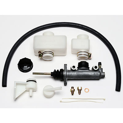 Bought it from this e-bay seller...still there and seems like a good deal. Wilwood 3/4 Then I pm'ed BIGKAT and Mike Bellis because I didn't understand how to connect the lines to the MC and Slave. BIGKAT reminded me that this isn't very complicated so I shouldn't over-think it and gave me several recommendations. Mike B. recommended using -3AN braided stainless PTFE hose. He also said NOT TO BUY THE CHEAP HOSE so I bought this: Aeroquip 10ft Aeroquip is good stuff. Bought 10 feet because Mike pointed out that unless I left some slack I would have to disconnect, drain, reconnect and re-bleed the clutch every time I dropped the engine. And with a conversion we're learning you have to do that a lot at the beginning. On the MC end you need this fitting: MC End Compression Fitting I also thought you needed another "adapter" fitting so I bought several others but this screws right into the fitting that comes with the MC. For the Subie slave you need a 10MM Banjo fitting I bought this one: Banjo Fitting One thing you should know is that it is thicker than the stock Subie fitting, which means you may have to take some material off of it. I have both stock and this one and will post pics so you see what I mean. Might be a non-issue but if so it shouldn't be hard to shave a little off of the loop if need be. Think that's all I have but I'll check the box later today. I'll also post the pedal setup I was looking at copying...have that link marked somewhere...this is where you come in and show me how to do that. (IMG:style_emoticons/default/biggrin.gif) It's REALLLLY cold here so plenty of time to watch you work! |
|
|
|
| Mike Bellis |
Dec 15 2013, 12:03 PM
Post
#189
|
|
Resident Electrician Group: Members Posts: 8,345 Joined: 22-June 09 From: Midlothian TX Member No.: 10,496 Region Association: None |
QUOTE(Chris H. @ Dec 13 2013, 11:18 AM) Now for the shocker...I COPIED MIKE BELLIS AND BIGKAT. I don't recommend copying anything I do. It might get you in trouble, or worse. What the hell do I know? (IMG:style_emoticons/default/blink.gif) (IMG:style_emoticons/default/screwy.gif) Actually, glad I could help. I'm always watching these threads for ideas to steal. (IMG:style_emoticons/default/cheer.gif) |
|
|
|
| Chris H. |
Dec 15 2013, 12:24 PM
Post
#190
|
|
Senior Member Group: Members Posts: 4,030 Joined: 2-January 03 From: Chicago 'burbs Member No.: 73 Region Association: Upper MidWest |
I admire your modesty Mike. You probably don't realize how helpful you are. The questions I asked you were very elementary based on your experience but you responded with a couple of paragraphs of clear, concise information. I only bugged you because there wasn't anything on the site at the time that explained the actual lines and fittings (use the "search" first everybody!) Hope I can help you out someday (IMG:style_emoticons/default/beerchug.gif) .
Hey Kent, here's the clutch setup I was looking at copying... PRS914-6 Clutch Looks like you flip the fork around the other way and attach it to the MC pin, then cut a hole in the floor (yikes) so it sits similar to the brake MC. LOOKS pretty straight forward but...we'll see. That bracket would be fairly easy to make I would think. Is this the setup you were looking at? |
|
|
|
| Chris H. |
Dec 15 2013, 01:01 PM
Post
#191
|
|
Senior Member Group: Members Posts: 4,030 Joined: 2-January 03 From: Chicago 'burbs Member No.: 73 Region Association: Upper MidWest |
OK last one...Here's that banjo fitting...measured them and the thickness difference is only 1.5MM so it may not be a big deal.
This is the stock fitting compared to the banjo fitting available at Summitracing. Bought the stock setup before I knew what I was doing. You COULD buy the stock fitting (has about 15 inches of braided hose and a threaded end) and then just do a screw-on connector at the end of it. To me that's just another point of failure so just doing the pressure fitting. Plus the stock setup is about $30...with either fitting you need a couple of copper washers for top and bottom as well. 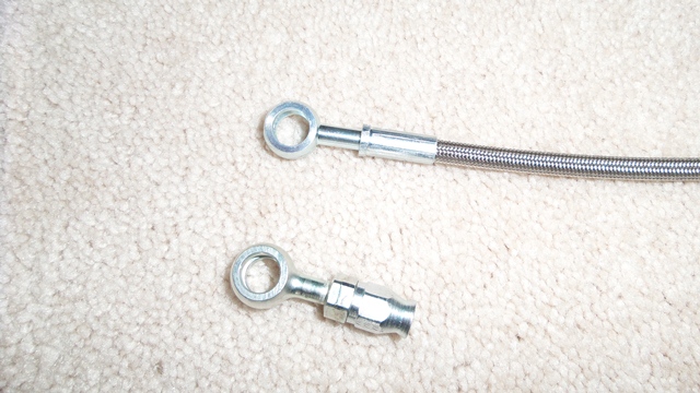 Height: 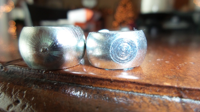 Another angle: 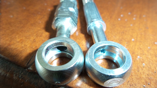 |
|
|
|
| 76-914 |
Dec 16 2013, 12:48 PM
Post
#192
|
|
Repeat Offender & Resident Subaru Antagonist Group: Members Posts: 13,502 Joined: 23-January 09 From: Temecula, CA Member No.: 9,964 Region Association: Southern California |
Wow, your a bloody plethora of info Christopher. I ordered the Wilton cylinder this AM. Before I order from Summit, I thought I would ask how the fitting is joined to the hose. Are mandrels req'd for joining? Yea, I had that write up too but wasn't sure about which mstr cyl to use. I'll note the measurements when I make it and we can exchange notes. I hear you about that cold weather. My shop heater is due in tomorrow. Just in the nick of time. It's been in the 40's & 50's here until this weekend (IMG:style_emoticons/default/happy11.gif) . And Mike, there's no shame in stealing great ideas. At least I hope not. (IMG:style_emoticons/default/lol-2.gif) After all, emulation is the most sincere form of flattery.
|
|
|
|
| Chris H. |
Dec 16 2013, 01:06 PM
Post
#193
|
|
Senior Member Group: Members Posts: 4,030 Joined: 2-January 03 From: Chicago 'burbs Member No.: 73 Region Association: Upper MidWest |
QUOTE(76-914 @ Dec 16 2013, 12:48 PM) Before I order from Summit, I thought I would ask how the fitting is joined to the hose. Are mandrels req'd for joining? This is really why I bugged Mike originally. I didn't get how they were joined. It's a pressure fitting apparently...looks fairly easy to assemble. Don't think you need much more than a vice and a wrench and some sort of lubricant. I bought the lube they sell and it comes in a huge bottle...waaaay more than you could ever possibly need. Ever. Happy to send you some if you want just PM me your address. Check this video.... https://www.youtube.com/watch?v=PeeflgGlenY Yeah I'm really good at collecting info. Now I just need to DO SOMETHING WITH IT. |
|
|
|
| CptTripps |
Dec 16 2013, 02:51 PM
Post
#194
|
|
:: Punch and Pie :: Group: Members Posts: 3,584 Joined: 26-December 04 From: Mentor, OH Member No.: 3,342 Region Association: Upper MidWest |
Gas Tank Question: How are you getting ALL the metal shavings out of the tank? That seems like a scary place to have loose metal floating around. (Or will the filter grab it all?)
Just a question on how you're getting fluid to the clutch master: I'm adding a Wilwood master cylinder to the stock 914 cluster, and thinking about how I'm going to get the fluid there. Since there are two lines out of the brake reservoir, could I use one for the clutch? (With a T if the other IS being used for a return.) Just trying to think this through. The Wilwood that I bought has a integrated reservoir, so I was going to add an external. |
|
|
|
| Chris H. |
Dec 16 2013, 02:58 PM
Post
#195
|
|
Senior Member Group: Members Posts: 4,030 Joined: 2-January 03 From: Chicago 'burbs Member No.: 73 Region Association: Upper MidWest |
Hmmm...my initial response wasn't quite right so I overwrote it....ours has a remote reservoir....so you just find an attachment point in the trunk very similar to your brake fluid reservoir. Super easy. I wouldn't co-mingle your brake fluid with your clutch fluid...if you lose your clutch pressure your brakes could fail... Plus the Cap'n would have a flippin' heart attack. We don't want that. I'd see if you can add a remote reservoir to the one you have. There has to be some sort of conversion kit available....
This looks like one: Remote MC Not saying that's "the one" for you but just an example. Appears to be for large military vehicles....but you get the idea... (IMG:style_emoticons/default/biggrin.gif) |
|
|
|
| CptTripps |
Dec 16 2013, 03:47 PM
Post
#196
|
|
:: Punch and Pie :: Group: Members Posts: 3,584 Joined: 26-December 04 From: Mentor, OH Member No.: 3,342 Region Association: Upper MidWest |
Oh it's not a big deal to add one. I think I already bought the kit. Just thinking out loud.
|
|
|
|
| 76-914 |
Dec 16 2013, 08:47 PM
Post
#197
|
|
Repeat Offender & Resident Subaru Antagonist Group: Members Posts: 13,502 Joined: 23-January 09 From: Temecula, CA Member No.: 9,964 Region Association: Southern California |
[quote name='CptTripps' date='Dec 16 2013, 12:51 PM' post='1971290']
Gas Tank Question: How are you getting ALL the metal shavings out of the tank? That seems like a scary place to have loose metal floating around. (Or will the filter grab it all?) Before the 3 openings were closed I hit it with a brush, vacuumed and then stuck an air hose/blow gun in one opening my arm in another and blasted it with compressed air for a few minutes. |
|
|
|
| Mike Bellis |
Dec 16 2013, 11:20 PM
Post
#198
|
|
Resident Electrician Group: Members Posts: 8,345 Joined: 22-June 09 From: Midlothian TX Member No.: 10,496 Region Association: None |
QUOTE(CptTripps @ Dec 16 2013, 12:51 PM) Since there are two lines out of the brake reservoir, could I use one for the clutch? (With a T if the other IS being used for a return.) NO! NO! NO! Don't mess with the brake reservoir. If you want to go this route, use a reservoir from a car designed to share with the clutch. Very hard to find. Some Japanese cars did this. The tap for the clutch fluid is near the top of the reservoir. So if it fails you still have brake fluid. If you use a T on the factory reservoir and it fails, you loose your brakes!!! I spent the day at Pick & Pull and could not find one I liked. I used the Wilwood reservoir since my brakes work very well. Why FUCH with it? |
|
|
|
| 76-914 |
Jan 4 2014, 11:46 AM
Post
#199
|
|
Repeat Offender & Resident Subaru Antagonist Group: Members Posts: 13,502 Joined: 23-January 09 From: Temecula, CA Member No.: 9,964 Region Association: Southern California |
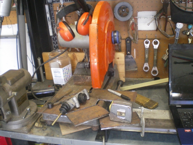
I've been putting this off as I do with all things that confuse me. (IMG:style_emoticons/default/biggrin.gif) It felt like waiting for school to let out so the class bully could whip my ass. (IMG:style_emoticons/default/dry.gif) But just like the proverbial ass whupping, "it 'twern't that bad." Thx to PRS914-6 for previously posting what he had done with the hydraulic set up. It was invaluable. I'm making 2 of these. One for Chris and one for me. Why? Chris is a good guy and has saved me me countless hours thru his perusing Suby articles and............ if it turns to (IMG:style_emoticons/default/stromberg.gif) Chris will know it before me because his project is ahead of mine. Devious, yes? (IMG:style_emoticons/default/biggrin.gif) Enough Pontificating! Here's how it's done. I used (as always) some scrap 3/16" plate steel and cut it into a few small sections as seen in this pic.
 Then just keep them stacked as the holes are drilled out. This is faster (until one realizes that the prototype is wrong (IMG:style_emoticons/default/happy11.gif) ) and insures correct duplication. 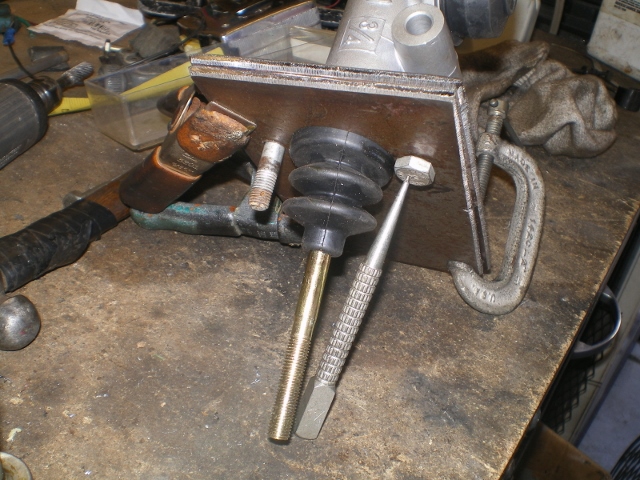 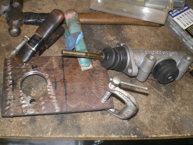 Some quick test fitting before I go much further........... 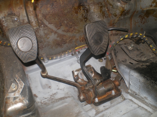 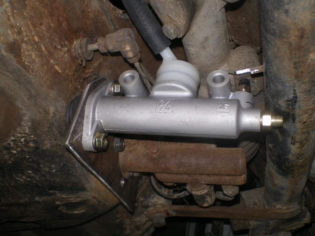 and to locate a spot to hang the reservoir. Real estate beneath the front hood is becoming scarce since I began this conversion. But the hose supplied by Wilwood was the "exact" length necessary. Crazy, huh? 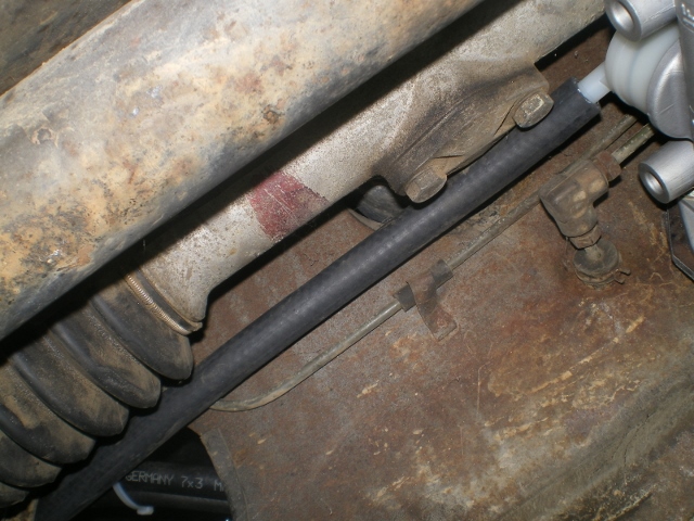 While I'm in here I think I see a simple solution to the dreaded "brake flex" that I read about. I took this $3.18 weld tab (in SoCal. probably .35 everywhere else) and trimmed appx 1/8" of the tips so that it would set flush against the steering bar.... 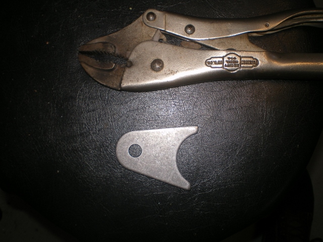 a quick polish to prevent cracking 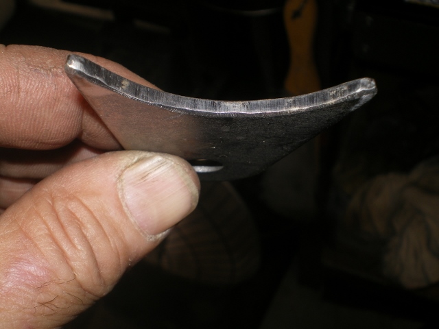 Then enlarge the existing holes to 8mm (5/16") to match the hole in the weld tab. I'll enlarge both holes although I only need one. Future use. (IMG:style_emoticons/default/idea.gif) 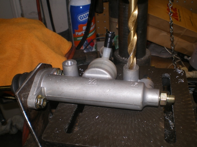 looking good 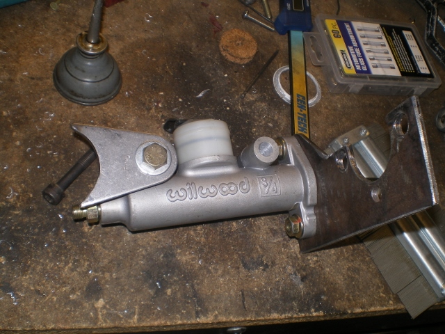 The original mounting plate is now trimmed to %80 of it's final shape 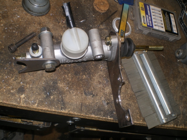 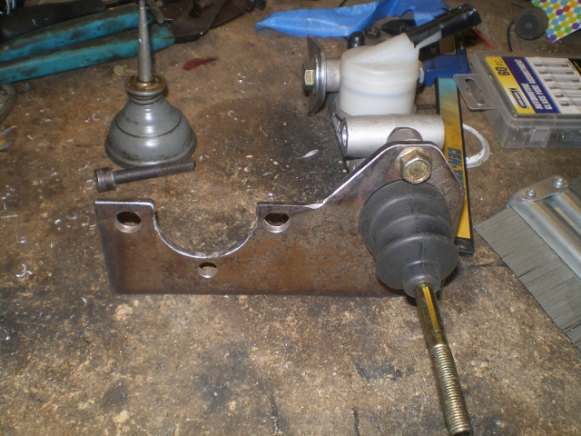 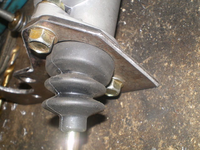 I needed to enlarge this plastic bushing to 8mm. Don't try this with a regular 8mm bit. Step drill it with a graduated bit or a suitably fluted bit for plastic. Otherwise, you'll destroy this bushing. 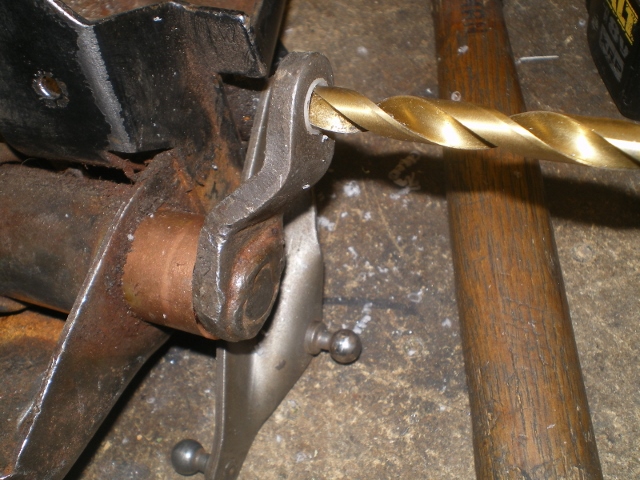 A few mocked up shots. The Heim joint shown will be replaced with a clevis fitting. Otherwise it is offset too much for my taste. 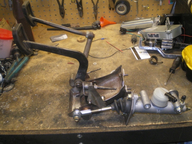 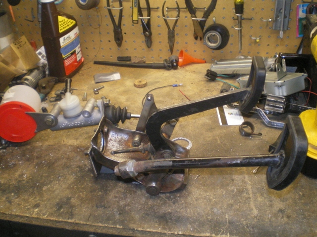 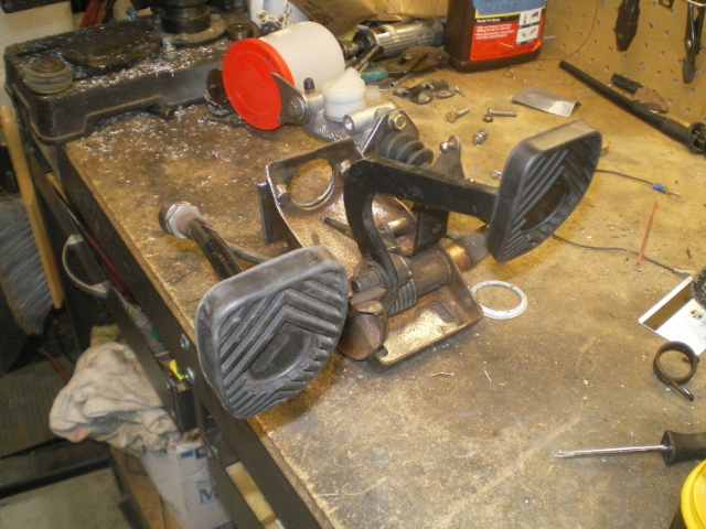 I'm happy with the fit for now but I'm not so sure that I won't add something to dampen the sound transfer at some point. 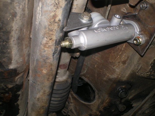 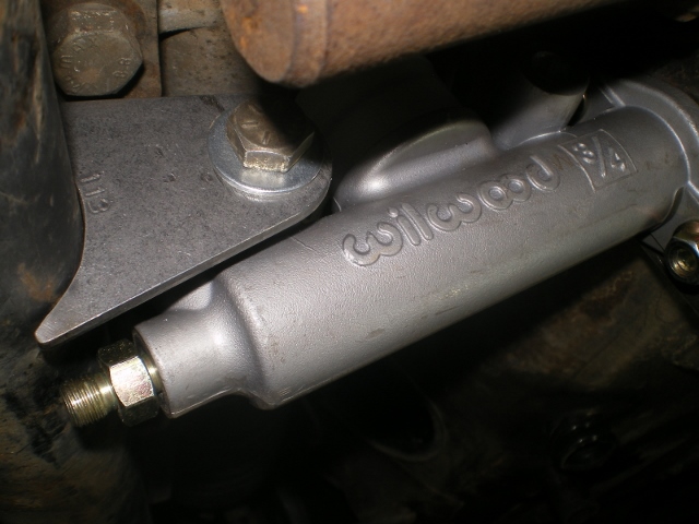 Attached image(s) 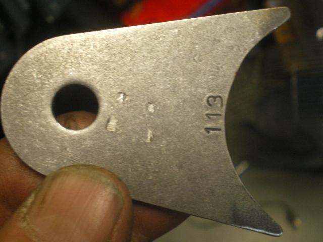
|
|
|
|
| 76-914 |
Jan 4 2014, 12:01 PM
Post
#200
|
|
Repeat Offender & Resident Subaru Antagonist Group: Members Posts: 13,502 Joined: 23-January 09 From: Temecula, CA Member No.: 9,964 Region Association: Southern California |
As mentioned earlier, the hose supplied was just the right length. I used the tab afixed to the tank to mount the reservoir. This took a few minutes as there is not a mm to spare. This manilla paper is almost too thick to squeeze in between.
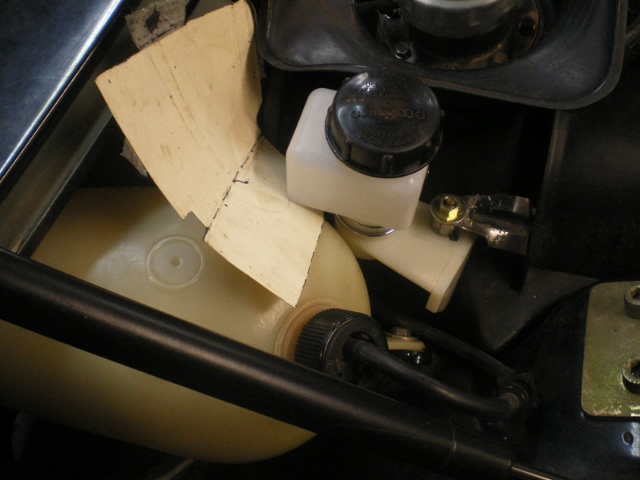 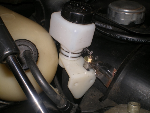 Here is your mount, Chris. After the proto is final I will trim it and mail it off to you. 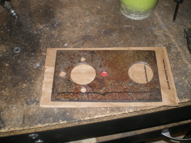 Some more with it in place. This is pretty much it except for the clevis joint which will be installed in place of the Heim joint; the hose still needs to be slid into place and connected and of course it will need to be tested. If anyone is interested I'll post the dimensions next time. 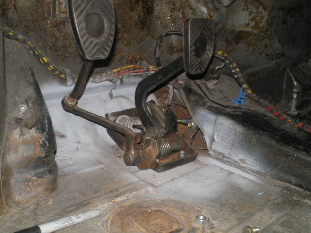   Attached image(s) 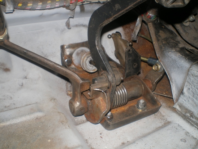 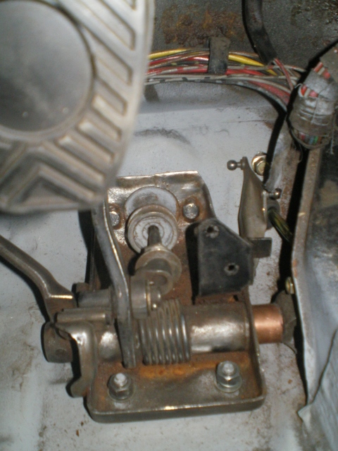
|
|
|
|
|
1 User(s) are reading this topic (1 Guests and 0 Anonymous Users)
0 Members:

|
Lo-Fi Version | Time is now: 17th May 2024 - 02:11 PM |
Invision Power Board
v9.1.4 © 2024 IPS, Inc.